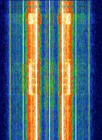
STP403 Bus PIT System
Description[edit]
STP403 is a bus PITPassenger Information Terminals, such as bus timetable displays at bus stops system used to update digital displays at bus stops. STP403 was developed by French companies INEO and CESATEC. STP403 sends data such as arrival time of buses.
Also seen in France at 164 MHzMegaHertz (MHz) 10^6 Hz, and at 469 MHzMegaHertz (MHz) 10^6 Hz close to an MPT1327 control channel used for bus transport.
After a little reverse-engineering, it seems this is a downlink channel used by Keolis to communicate with bus displays in France.
It serves multiples purposes :
- update various informations used by the bus display firmware : informations of the lines (bus number, name of destination), formatting strings... This is done once a day, around 3 AMAmplitude Modulation.
- send the time
- update the arrival time of buses at each stop.
Remark : the layer 3 protocol is used in other cities over TETRA to send the same informations.
Modulation[edit]
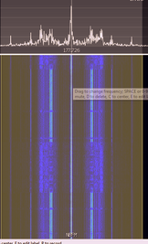
The modulation is FMFrequency Modulation modulated FFSKFast Frequency-Shift Keying at 1200 bit/sBits per second (bps) : the mark (1) and space (0) frequencies are 1200/1800 HzHertz (Hz), unit of frequency, defined as one cycle per second (1 Hz)..
Demodulation[edit]
Since it's FFSKFast Frequency-Shift Keying, you can get the bit stream by multiplying the signal with a version of itself delayed by one period, and applying a low-pass filter :
mpg123 -r 48000 -0 -w resampled.wav Fouine91_MPT1327-Like.mp3
sox --norm --combine multiply resampled.wav "|sox resampled.wav -p delay 40s" out.wav lowpass 1200
Here is the resulting wav file :
You can open it in Audacity and read the decoded bits (1 bit every 40 frames).
Bit decoding[edit]
The binary data is encoded like a serial port with parameters 1200Hz/8-N-1.
A byte is encoded by a starting bit (0) followed by the bits lsb-first, and a stop bit (1). When there is no data to send, only 1s are transmitted.
Layer 1[edit]
The received bytes seem to be cut in frames. The beginning of a frame can be detected by a number of stop bits longer than usual (>= 10 ?), and the first byte which is 0x10.
Once cut info frames, the data looks like this :
10 44 00 49 1D FF FF FF FF FF FF FF
10 43 00 FF AC FF 5C 8E 17 C5 ED 24
10 44 00 0F 5B 51 80 38 38 36 30 32
10 43 49 FF E5 20 20 38 36 30 32 20
10 44 77 B6 95 20 10 10 1E 01 00 00
10 43 0F FF A3 51 F0 37 1F 81 FF FF
10 44 00 8E DA FF FF FF FF FF FF FF
10 44 B6 A9 4B FF FF FF FF FF FF FF
10 4C 8E 8E 5C FF FF FF FF FF 5C D1 01 8C EE 04 03 E0 BB FF FF
10 44 00 D1 85 FF FF FF FF FF FF FF
...
Each frame begins by a 5 bytes header, followed by data bytes.
The format of the header is as follow :
- 1st byte : start of frame (0x10)
- 2nd byte : ???
- 3rd byte : ???
- 4th byte : ???
- 5th byte : XOR of four previous bytes
The data stream is obtained by concatenating the data bytes of every frame, and replacing every occurrence of '0x10 0x10' by a single '0x10' byte. (The 0x10 byte is only escaped in the data bytes, and not in the header).
The resulting data stream for the above data is :
FF FF FF FF FF FF FF FF 5C 8E 17 C5 ED 24 51 80 38 38 36 30 32 20 20 38 36 30 32 20 20 10 1E 01 00 00 51 F0 37 1F 81 FF FF FF FF FF FF FF FF FF FF FF FF FF FF FF FF FF FF FF FF FF 5C D1 01 8C EE 04 03 E0 BB FF FF FF FF FF FF FF FF FF
Layer 2[edit]
The data stream consists of datagrams padded by optional 0xFF sequences (when there is nothing to transmit ?).
Datagrams begin by a 6-byte header, followed by data, and a 16 bit CRC of the entire datagram.
The previous stream contains the following datagrams :
5C 8E 17 C5 ED 24 51 80 38 38 36 30 32 20 20 38 36 30 32 20 20 10 1E 01 00 00 51 F0 37 1F 81
5C D1 01 8C EE 04 03 E0 BB
The header is as follows :
- 1st and 2nd byte : destination address (53 FF is broadcast)
- 3rd byte : number of data bytes
- 4th byte : XOR of three previous bytes
- 5th byte : message number
- 6th byte : flags
The message number is incremented by one for each new message, except if it is a retransmission.
The only bit known in the flags field is the 6th bit (0x40). If it is set, it means that the datagram is part of a segmented transmission.
A fragmented layer 3 packet is transmitted in several layer 2 datagrams. Each of these packets will have the "fragmented" flag set in the flags field (0x40). If the 6th bit (0x40) of the flags field is set, it means the datagram is part of a fragmented layer 3 packet. The data bytes start with two additional fields :
- 1st byte : frag flag. A value of 0x80 indicates a new fragmented frame ; a value of 0x00 indicates continuation ;
- 2nd and 3rd bytes : remaining length. This is the number of bytes left to transmit.
Layer 3[edit]
An unsegmented layer 3 packet starts with a 1-byte opcode, followed by the data bytes.
| Field | Opcode | Data... |
|---|---|---|
| Size | byte | variable |
It the layer 3 packet is too large to fit in a single layer 2 datagram, it is segmented into several datagrams. Each datagram has the frag flag (0x40) set. Also, each of the layer 3 packets will have the following layout :
| Field | Opcode | Flags | Remaining | Data... |
|---|---|---|---|---|
| Size | byte | byte | word | variable |
The value of the flags field is 0x80 for the first packet, and 0x00 for the others. The Remaining field indicates how many bytes are left to transmit.
The original packet is obtained by concatenating every data bytes, and prepending the Opcode.
Destinations informations (0x23)[edit]
This message is sent to all stations to send informations about bus directions. A bus directions is composed of :
- a unique identifier
- the number of the bus
- the name of the possible destinations in that direction.
| Field | 02 | UpdateId | Strsize | N | Directions... |
|---|---|---|---|---|---|
| Size | byte | byte | byte | byte | variable (repeat: N) |
Each record corresponds to the direction of a bus line.
| Field | Id | Bus Number | Num destinations | Destination name... |
|---|---|---|---|---|
| Size | byte | 4 chars | byte | Strsize chars |
Messages and formatting informations (0x22)[edit]
Arrival update (0x27)[edit]
This packet is sent at regular intervals to every PITPassenger Information Terminals, such as bus timetable displays at bus stops to update the arrival time of the buses. The data for all the PITs is contained packed in a single big packet sent to broadcast.
| Field | UpdateId | TxNum | PitInfo... |
|---|---|---|---|
| Size | byte | byte | Variable (repeat: until end) |
| Field | InfoSize | Arrival... |
|---|---|---|
| Size | byte | word (repeat: InfoSize/2) |
Individual arrival update (0x28)[edit]
This message is sent to a single PITPassenger Information Terminals, such as bus timetable displays at bus stops to update the arrival time.
| Field | UpdateId | TxNum | Arrival... |
|---|---|---|---|
| Size | byte | byte | word (repeat: until end) |
Status request (0x25)[edit]
This packets is used to get the state of a particular PITPassenger Information Terminals, such as bus timetable displays at bus stops.
This message has no additional data.
Perturbation info (0x29)[edit]
This is used to display a specific messages on the PITPassenger Information Terminals, such as bus timetable displays at bus stops.
| Field | Message... |
|---|---|
| Size | PString (repeat: 6) |
Time information (0x71)[edit]
| Field | Year - 1900 | Month | Day | Hour | Minute | Seconds | Day of week |
|---|---|---|---|---|---|---|---|
| Size | byte | byte | byte | byte | byte | byte | byte |
Example : 71 74 02 18 01 2B 2F 03
Antennas[edit]
Discone Scanmaster.

